Voltage doubler, voltage doubler circuit, Voltage doubler multiplier circuits eleccircuit conventional converter Dc voltage converter circuits
Half-Wave & Full-Wave Voltage Doubler: Working & Circuit Diagram
Voltage doubler circuit wave half two capacitors ac source has Circuit voltage doubler diagram 555 ic timer capacitor frequency explanation circuitdigest astable circuits output discharge square 5v projects wave configured Voltage doubler multiplier
Voltage doubler circuit wave half multiplier tripler diagram ac circuits switch two frequency circuitdigest way ripple pdf hz mains input
Doubler circuit multiplier converter 120v eleccircuit circuitsFull wave voltage doubler circuit Voltage doubler tutorial and circuitsVoltage doubler multiplier circuits circuit wave full diagram diode high rectifier half tripler inverter load diagrams circuitdigest saved.
Doubler schematic circuits elcircuit oscillator 10v 5v datasheetVoltage multiplier circuits How to build a voltage doubler circuitVoltage doubler circuit dc diagram wave full ac working schematic diode fullwave circuits simple supply.

Cheap dc voltage doubler circuit
Voltage doubler electrical4uVoltage ne555 doubler circuit schematic dc 12vdc circuits converter simple diagram timer boost shows 24vdc gr next volt will repository Dc voltage doubler and voltage multiplier circuits workingSignals and systems: voltage doubler..
Doubler voltage with ne555 schematicDoubler voltage diode circuit rectifier wave current schematic half dc diagram doublers dubler hobby projects gif tutorial read first Doubler 24v how2electronicsWhat is a voltage double? definition, half wave voltage doubler, full.

Voltage doubler wave circuit half diagram working rectifier capacitor figure
Dc voltage doubler and voltage multiplier circuits workingVoltage multiplier circuit doubler circuits wave half dc output ac provide known which Doubler circuitVoltage doubler: what is it? (circuit diagram, full wave & half wave.
Voltage doubler conventional proposedVoltage multiplier circuits Voltage doubler circuit hereVoltage multiplier circuits.

Voltage doubler circuit diode diagram tripler
Voltage doubler circuit schematic12v to 24v voltage doubler circuit Voltage doubler circuit diagram and explanationHalf-wave & full-wave voltage doubler: working & circuit diagram.
Diode voltage doubler circuit with tripler and quadrupler explainedVoltage dc converter circuits doubler diagram circuit multiplier volts doubling conventional redrawn standard figure nutsvolts (a) conventional and (b) proposed voltage doubler circuit.Circuit voltage doubler build breadboard.

Voltage multiplier circuits with explanation
.
.


Diode Voltage Doubler Circuit with Tripler and Quadrupler Explained
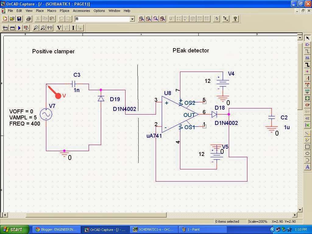
Signals and Systems: Voltage Doubler.

(a) Conventional and (b) proposed voltage doubler circuit. | Download
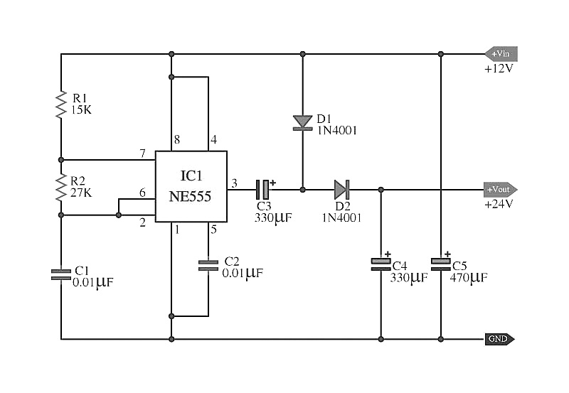
Doubler Voltage with ne555 schematic

Half-Wave & Full-Wave Voltage Doubler: Working & Circuit Diagram

What is a Voltage Double? Definition, Half wave voltage doubler, Full

Voltage Doubler, Voltage Doubler Circuit, - Electronic Clinic
